The mixer truck heat-exchanger is a critical component of the hydraulic system and engine cooling system in concrete mixer trucks. Operating in harsh environments (vibration, dust, slurry), it demands exceptionally high standards for strength, sealing integrity, heat dissipation efficiency, and corrosion resistance. Its manufacturing process integrates multiple technologies including sheet metal fabrication, welding, vacuum brazing, and seal testing.
The typical manufacturing process for mixer truck heat-exchanger is generally divided into two major stages: core assembly production and final assembly. A detailed description of the manufacturing process follows below.
Core Assembly Manufacturing
The core assembly serves as the heart of the heat sink, responsible for heat exchanger. The most common structure on the market is the plate-fin type.
Material Preparation
Composite Plate: The current mainstream trend favors aluminum alloy due to its light weight, excellent heat dissipation properties, and relatively low cost. Commonly used thickness is 0.5mm double-sided clad plate.
Heat Spreader: Extremely thin aluminum foil, typically rolled into a corrugated pattern (corrugated strip) or perforated with louvered openings to increase surface area and disrupt airflow, enhancing heat dissipation efficiency. Industry standards currently favor thicknesses of 0.15mm and 0.17mm.
Sealing strips: Extruded from molded profiles, common heights on the air side include 12, 10.3, 9.5, and 8 mm, while oil side heights include 3.0, 2.5, 2.0, and 1.6 mm.
Part Cleaning
To remove oil contamination from parts, common cleaning methods include acid/alkali washing, ultrasonic cleaning, hydrocarbon cleaning, and modified alcohol cleaning. Ultrasonic cleaning provides a technical solution for removing strongly adhered contaminants. This cleaning process generates powerful physical cleaning effects. Prior to core assembly, fins, composite panels, and sealing strips must undergo ultrasonic cleaning to eliminate dirt and oil residues.
Core Assembly
Procedure: Place one fin on a MPE(Micro Port Extrusion), then position another MPE atop it to form a basic unit. Stack the basic units and sealed with inlet manifold and return manifold to create the core of a plate-fin heat exchanger.
Key Point: Ensure uniform and tight assembly gaps between all components, as this forms the foundation for subsequent brazing quality.
Core Brazing
This is the most critical and technically demanding step in the entire process, with vacuum brazing currently being the most widely adopted method.
Loading: Place the assembled core into the vacuum brazing furnace.
Evacuation and Heating: Evacuate the furnace to a vacuum state (to prevent metal oxidation), then heat according to a precise temperature ramp curve.
Brazing: When the temperature reaches the brazing filler metal’s melting point (slightly below the base material’s melting point), the filler metal melts and fills all contact gaps via capillary action, firmly bonding the main plate, cooling tube, and heat dissipation strip into a single unit.
Cooling and Removal: After program-controlled cooling, the formed core assembly is removed from the furnace.
Advantages: Smooth welds, high strength, excellent corrosion resistance. Capable of simultaneously welding thousands of connection points with high efficiency and consistent quality.
Disadvantages: Extremely high requirements for part precision and cleanliness.
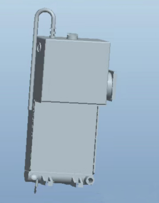
Assembly
Assemble the core body with other functional components to form a complete heat-exchanger assembly.
Oil Chamber Assembly and Welding
Water Chamber/Oil Chamber: The inlet/outlet cavity for coolant or hydraulic oil, typically made of aluminum alloy.
Welding: Aluminum alloy water chamber/oil chamber: Welded to the core body using TIG welding or MIG welding. This welding process demands high operator skill to ensure continuous, uniform welds with no leakage.
Leak Testing
This is a mandatory 100% inspection procedure.
Method: Seal off each channel of the radiator (water channels, oil channels) individually. Introduce compressed air or nitrogen at a specified pressure (typically 1.5 to 2 times the working pressure). Then submerge the entire radiator in a water tank and observe for any bubbles emerging.
Purpose: To verify the integrity of all welds and seals, ensuring no leakage points exist.
Surface Treatment and Coating
Cleaning: Removal of oil contamination and welding residues.
Pre-treatment: Such as phosphating (for steel components) or passivation (for aluminum alloys) to enhance coating adhesion and improve corrosion resistance.
Spray Painting/Powder Coating: Utilizing epoxy or polyester coatings with excellent weather resistance and anti-corrosion properties. Electrostatic powder coating is a commonly employed process, delivering uniform, durable, and aesthetically pleasing coatings.
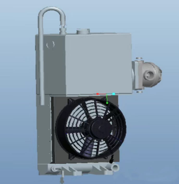
Assembly
Perform final assembly of the air duct, filter, thermostat, and fan unit.
Power-On Operation Test
Power on the fan for operation to ensure normal functioning with no abnormal noises.
Final Inspection and Packaging
Conduct visual inspection to confirm no dents or scratches.
Verify model number and interface dimensions.
Use specialized packaging materials (e.g., foam, wooden crates) to prevent damage to precision cooling fins during transit.